Linear modules are widely used in industrial automation to move components, tools, workpieces, and fixtures along a controlled straight path. They are essential in applications such as automated assembly, pick-and-place equipment, inspection systems, packaging machinery, and precision positioning systems.
Understanding the working principle of linear modules helps engineers and equipment manufacturers select the right motion solution for their applications. Different modules use different drive mechanisms, but they share a common purpose: converting a drive input into controlled linear movement while guiding and supporting the moving load.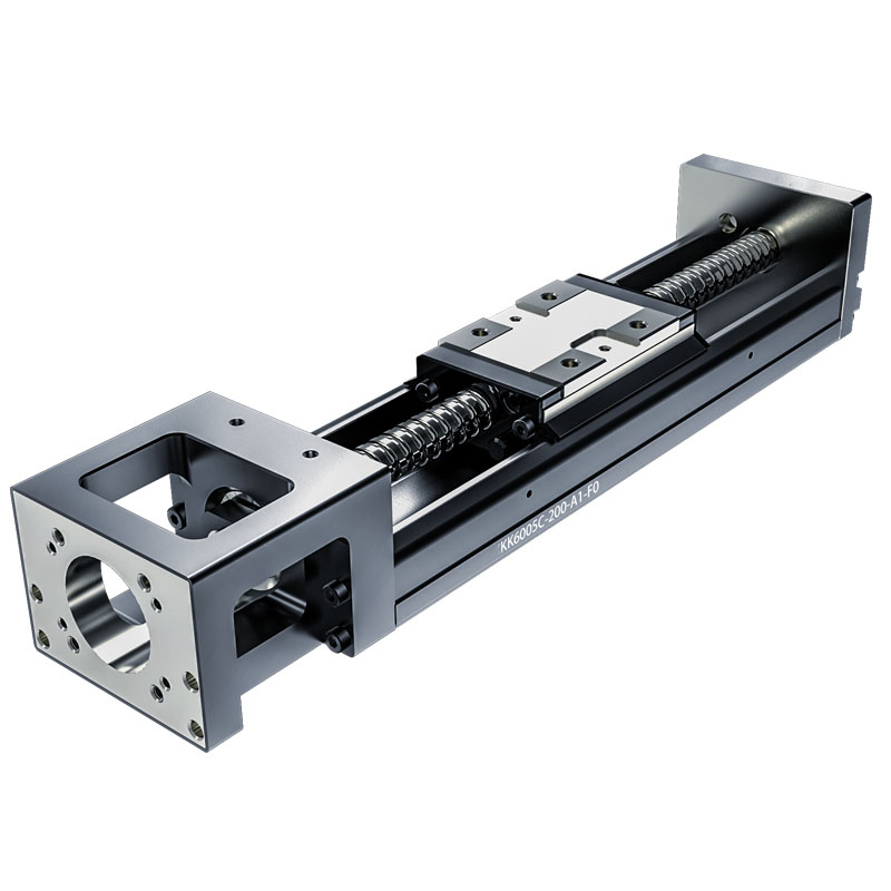
This article explains how linear modules work, their main components, the differences between common drive types, and the factors to consider when selecting a module for custom automation equipment.
A linear module is an integrated mechanical motion unit designed to provide controlled linear movement. It typically combines a structural frame, linear guide, drive mechanism, moving carriage, and motor or motor interface.
Depending on the design, a linear module may use a timing belt, ball screw, rack and pinion, or linear motor to generate motion.
Compared with building a linear motion system from separate components, an integrated module can simplify mechanical design, installation, and alignment. It can also be incorporated into single-axis or multi-axis automation equipment.
Typical applications include:
Automated loading and unloading.
Pick-and-place and material handling.
Dispensing, cutting, and laser processing.
Machine vision and inspection.
Electronic component assembly.
XYZ gantry systems.
Automated production and testing equipment.
The appropriate module depends on the required stroke, payload, speed, positioning performance, installation space, and operating environment.
The working principle of a linear module is based on converting an input drive motion into controlled linear displacement. The exact conversion method depends on the drive mechanism.
In a motor-driven module, the motor generates rotary motion. A mechanical transmission system then converts this motion into linear movement, causing the carriage to travel along the guide rail.
The basic operating process consists of four steps.
Step 1: The motor generates motion
A servo motor, stepper motor, or other suitable drive source provides the input motion according to the machine's control commands.
Step 2: The drive mechanism transmits motion
A belt, ball screw, rack and pinion, or direct-drive system transfers the motor's motion to the moving carriage.
Step 3: The guide system constrains movement
Linear guides support the carriage and help maintain a defined travel path while handling the loads specified for the module.
Step 4: The carriage reaches the target position
The control system regulates motor movement to achieve the commanded position and speed. Feedback devices may be used to monitor and correct positioning errors.
For example, in a ball screw linear module, the motor rotates the screw while the nut is connected to the moving carriage. As the screw rotates, the nut travels along the screw axis, moving the carriage in a straight line.
The relationship between motor rotation and linear travel depends on the transmission design. The final positioning performance also depends on mechanical rigidity, backlash, feedback resolution, load, and control settings.
A linear module's performance depends on the interaction between its mechanical and electrical components.
|
Component |
Main Function |
|---|---|
|
Structural frame |
Supports the module and maintains mechanical alignment |
|
Linear guide rail and carriage |
Guides movement and supports specified loads |
|
Drive mechanism |
Converts or transmits input motion into linear displacement |
|
Motor |
Provides the power needed to move the carriage |
|
Coupling or transmission interface |
Transfers motion between the motor and drive mechanism where required |
|
Controller and drive |
Regulate motion, acceleration, speed, and positioning |
|
Encoder or feedback device |
Provides position or motion feedback when used |
|
Limit switches and sensors |
Detect travel limits or machine conditions where required |
Not every linear module uses the same component arrangement. For example, a direct-drive linear motor module does not require a rotary motor to drive a ball screw or belt. Some modules also integrate the motor and drive system into a compact assembly.
Correct component selection is important because the guide, drive mechanism, frame, and motor must work together to meet the machine's operating requirements.
A belt-driven linear module uses a timing belt connected to a motor-driven pulley. The carriage is attached to the belt, so the belt's movement drives the carriage along the guide system.
When the motor rotates the pulley, the belt moves and transfers the motion to the carriage.
Main characteristics:
Suitable for relatively long travel distances.
Supports high-speed movement in appropriately designed systems.
Can provide a compact and cost-effective solution for many transfer applications.
Requires consideration of belt tension, elasticity, wear, and load conditions.
Belt-driven modules are commonly used in material handling, packaging, loading and unloading, and multi-axis gantry systems where travel distance and cycle time are important.
A ball screw linear module converts the rotary motion of a screw into linear movement through a ball nut. The balls circulate between the screw and nut to reduce friction compared with conventional sliding screw arrangements.
When the motor rotates the screw, the nut moves along its axis and carries the attached carriage.
Main characteristics:
Suitable for controlled positioning and applications requiring relatively high stiffness.
Can provide high thrust depending on the screw size, lead, motor, and system design.
Supports a range of positioning requirements when paired with suitable feedback and controls.
Requires attention to lubrication, screw critical speed, buckling, and service life.
Ball screw modules are frequently used in precision assembly, inspection equipment, machine tools, and automated positioning systems.
A gear rack linear module uses a rotating pinion gear that engages with a straight rack. As the pinion rotates, it travels along the rack or drives the rack in a linear direction, depending on the mechanical arrangement.
Main characteristics:
Suitable for applications requiring long travel.
Can be designed for substantial loads and demanding industrial environments.
Offers flexibility in configuring long-axis motion systems.
Requires consideration of gear backlash, lubrication, alignment, and transmission accuracy.
Gear rack modules are used in larger automation equipment, gantry systems, and applications where long travel and load requirements influence the drive selection.
A linear motor generates force directly along a straight path rather than first producing rotary motion and converting it through a screw or belt.
The motor's electromagnetic force drives the moving part along the guide system. A suitable controller and position feedback device can regulate the movement.
Main characteristics:
Direct-drive motion without a rotary-to-linear transmission.
Potential for high acceleration and dynamic response.
Suitable for demanding positioning and motion-control applications.
Requires careful consideration of thermal management, motor sizing, feedback, and control integration.
Linear motor modules are used in high-speed inspection, electronics manufacturing, precision handling, and other applications that require dynamic motion performance.
|
Feature |
Belt-Driven |
Ball Screw |
Gear Rack |
Linear Motor |
|---|---|---|---|---|
|
Motion conversion |
Belt and pulley |
Screw and ball nut |
Pinion and rack |
Direct electromagnetic drive |
|
Typical strength |
Long travel and speed |
Controlled positioning and thrust |
Long travel and load flexibility |
Dynamic response and direct drive |
|
Positioning performance |
Depends on belt, feedback, and system design |
Depends on screw, feedback, and system design |
Depends on gear quality, backlash, and feedback |
Depends on motor, feedback, and control |
|
Key considerations |
Belt tension and elasticity |
Screw life and critical speed |
Backlash and lubrication |
Heat and drive requirements |
|
Common applications |
Transfer and gantry systems |
Precision assembly and positioning |
Large equipment and long axes |
High-speed precision automation |
There is no single drive type that is best for every application. A suitable selection balances travel distance, payload, speed, positioning requirements, cost, maintenance, and installation conditions.
Positioning performance is determined by more than the motor or drive mechanism alone. It depends on the mechanical structure, transmission system, feedback device, controller, and operating conditions.
Several factors are particularly important.
Drive mechanism: Screw lead, belt elasticity, gear backlash, and transmission stiffness influence how accurately motor motion is converted into carriage movement.
Position feedback: An encoder or linear scale can provide position information to the control system. The feedback arrangement affects the system's ability to detect and correct motion errors.
Mechanical rigidity: Frame stiffness, guide mounting, load distribution, and external forces influence deflection and repeatability.
Motion control: Acceleration, deceleration, settling time, and servo tuning can affect final positioning stability.
Operating conditions: Temperature, contamination, lubrication, vibration, and payload changes can influence performance over time.
It is also important to distinguish between positioning accuracy and repeatability. Accuracy describes how closely the actual position matches the commanded position, while repeatability describes how consistently the module returns to the same position under comparable conditions.
For applications such as semiconductor equipment, optical inspection, and precision assembly, engineers should define both requirements rather than relying on a general description such as "high precision."
Multi-Axis Gantry Systems
Multiple linear modules can be assembled into X, Y, and Z axes to position tools, components, and workpieces within a defined working area.
Pick-and-Place Equipment
Linear modules move grippers and products between loading, processing, and unloading stations. The selected configuration must meet the required cycle time and payload.
Inspection and Measurement
Controlled linear movement positions cameras, sensors, and samples for inspection. Mechanical stability and repeatability are important for consistent measurement.
Dispensing and Processing
Linear modules guide dispensing heads, cutting tools, or processing units along programmed paths. The drive type should match the required speed, path accuracy, and working stroke.
Automated Production Lines
Linear modules transfer components between workstations and can be integrated with conveyors, sensors, robots, and machine controllers to support coordinated production.
For equipment manufacturers and system integrators, choosing a linear module should begin with the actual machine requirements.
Determine the required travel distance and the available installation space. Consider not only the usable stroke but also the module's overall length and space needed for the motor and accessories.
Evaluate the moving mass, mounting orientation, acceleration, and any external forces or moments. The guide system, drive mechanism, and frame must all be suitable for the application.
Calculate the required travel speed, acceleration, deceleration, and total operating cycle. Maximum speed alone does not indicate how quickly the module can complete a full motion sequence.
Choose between belt, ball screw, gear rack, and linear motor technologies according to travel length, thrust, positioning requirements, dynamic performance, maintenance, and budget.
Identify the required accuracy, repeatability, feedback type, controller compatibility, and communication interface. These requirements should be considered early, especially in multi-axis systems.
Custom automation machinery may require a special stroke, mounting interface, motor orientation, protective cover, or multi-axis configuration. Confirm the available customization options with the manufacturer before finalizing the machine design.
Standard linear modules may not fit every machine layout or production requirement. OEM equipment manufacturers often need a customized motion solution that integrates with their mechanical structure, control system, and production process.
Customization may involve:
Stroke length and overall dimensions.
Belt-driven, ball screw, gear rack, or linear motor configurations.
Payload and speed requirements.
Motor selection and mounting orientation.
Sensor, limit switch, and feedback options.
Single-axis or multi-axis system integration.
Environmental protection and maintenance requirements.
KNK Technology provides linear motion products for industrial automation, including linear modules, electric cylinders, linear motor modules, and related motion solutions.
When selecting a linear module for a custom project, providing the manufacturer with the working stroke, payload, speed, positioning requirements, installation drawings, and control preferences can help identify a suitable configuration.
Explore KNK Technology's linear motion solutions to learn more about products for industrial automation and OEM equipment integration.